
Summary
I ran BeidPrep's midsurface engine (release engine 8cefff4, 27 Oct 2026) on eight moulded and cast test parts that I designed myself, and compared each result with the part's designed mid-surface. On six of the eight parts the result covers 97.3–99.6 % of the true midsurface with a mean thickness error of 0.015–0.030 mm, and 0.9–4.2 % of the mesh elements fail a crash-quality check (one part: 9.7 %). The two free-form gear housings are the weak spot: 72–74 %, because the engine leaves out curved walls whose thickness changes along the wall.
The test parts
All eight parts are my own synthetic parts, built for this test; none is a client part. Each is one closed, valid solid, built from simple solids and boolean operations in CadQuery / OpenCascade, with no wall thinner than 1.0 mm. Wall sizes follow common injection-moulding design rules (rib root 0.5–0.7 × wall, draft 0.5–1.5° per side, root fillets about 0.25 × wall).
| Part | What it is | Size (mm) | Walls (mm) |
|---|---|---|---|
| 1 Gearbox cover | plate with a stepped zone, domed boss rings, honeycomb and straight ribs, bosses with gussets, flange | 136 × 146 × 30 | 1.2–3.0 |
| 2 Carrier tray | decks, skirt, tower, mounting lugs, snap hooks | 224 × 143 × 121 | 1.2–2.5 |
| 3 Gear housing | walls, two floor levels, partitions, stepped bosses, rim tongue | 234 × 140 × 75 | 1.2–3.0 |
| 3B Gear housing, free-form | Part 3 with curved (free-form) walls and floor | 236 × 141 × 85 | 1.2–3.0 |
| 3C Gear housing, free-form with root fillets | 3B with R1 fillets at every rib root | 236 × 141 × 85 | 1.2–3.0 |
| 4 Blower scroll | spiral scroll wall, box, ribbed panel, ears | 260 × 326 × 81 | 1.2–3.0 |
| 5 Pedal bracket | web with a rib truss, rims, fins, mount flange | 256 × 204 × 36 | 1.4–3.0 |
| 6 Hinge bracket | asymmetric bracket: web joggled up to a deck, two hinge lugs, rib truss, bosses, bolt-down ears | 294 × 150 × 60 | 1.4–4.0 |
Ground truth. I do not compare against another midsurface program. While each part is built, every wall, rib, boss and gusset also records its designed mid-surface (the surface halfway through the wall, as drawn) and its design thickness. These surfaces are trimmed to the part (holes and windows cut out) and each ends exactly where it meets its neighbour's mid-surface; the curves where two of them meet are the expected junctions. For curved shells the mid-surface is the part's own outer skin moved inward by half the wall thickness, so fillets are exact; drafted ribs keep their tapering thickness. Two simplifications: a boss's mid-cylinder runs through its solid core down to the plate, and the R1 root fillets of 3C are not part of its ground truth (the band at each filleted root is left out of the thickness check).
How I measured
Each part goes through the engine exactly as BeidPrep runs it: one run, in its own process, with a 300 s time limit. I do no manual clean-up, repair or re-run on any part. The same fixed scoring script is used for every engine version.
- Coverage: the share of the true mid-surface area that has result surface within 0.5 mm, or a quarter of the wall thickness where that is larger.
- Thickness error: where the result covers the true mid-surface, the thickness the engine assigns minus the design thickness there. Mean: area-weighted over all features. Max: the largest single reading on any feature.
- Junctions: an expected junction counts as found only when the result reaches at least 80 % of the junction line, both walls are covered on either side, and the result faces on the two sides share an edge. A junction that is reached but not joined counts as missing, because the mesh would have a crack there.
- Gaps: open edges of the result that do not lie within 1.5 mm of an open edge of the true mid-surface (holes and slits the design does not have), grouped into spots 2 mm apart; I give the number of spots and their total length.
- Mesh: the result meshed by BeidPrep's beta mesher, quad-dominant, 2 mm elements, defaults, no clean-up. For each crash-quality check I give the share of elements that fail it: corner angles (tri 30–120°, quad 45–135°), aspect ratio > 5, warpage > 15°, skew > 60°, Jacobian < 0.6, taper > 0.5, shortest edge < 1 mm; also the share failing any check, the elements with a corner under 5°, and the faces the mesher could not mesh.
Results per part
Engine 8cefff4. Pictures: the CAD solid, then the midsurface (one colour per thickness) with its 2 mm mesh.
Totals. Mean coverage over the eight parts 92.2 % (six parts 97.3–99.6 %); junctions found 991 of 1,298; no face of any result fails OpenCascade's validity check in memory.
| Part | Coverage | Thickness error mean / max (mm) | Junctions | Elements failing any check | Elements < 5° | Unmeshed faces | Gap spots (open edge) |
|---|---|---|---|---|---|---|---|
| 1 Gearbox cover | 98.06 % | 0.017 / 1.18 | 362 / 450 | 9.65 % of 10,949 | 27 | 1 | 72 (701 mm) |
| 2 Carrier tray | 99.25 % | 0.022 / 1.64 | 123 / 129 | 1.90 % of 23,419 | 3 | 0 | 17 (520 mm) |
| 3 Gear housing | 99.63 % | 0.030 / 2.62 | 176 / 184 | 3.00 % of 24,515 | 68 | 9 | 50 (1,072 mm) |
| 3B Free-form housing | 73.67 % | 0.048 / 2.57 | 46 / 128 | 1.05 % of 17,894 | 5 | 2 | 74 (2,254 mm) |
| 3C Free-form, root fillets | 72.32 % | 0.041 / 2.57 | 40 / 128 | 1.37 % of 17,534 | 3 | 2 | 84 (2,445 mm) |
| 4 Blower scroll | 97.30 % | 0.015 / 2.85 | 107 / 140 | 0.86 % of 30,662 | 5 | 0 | 30 (2,562 mm) |
| 5 Pedal bracket | 98.87 % | 0.023 / 3.89 | 85 / 86 | 4.21 % of 11,345 | 5 | 0 | 28 (1,136 mm) |
| 6 Hinge bracket | 98.20 % | 0.020 / 2.79 | 52 / 53 | 1.40 % of 15,120 | 1 | 2 | 17 (906 mm) |
Share of elements failing each check (%):
| Part | Angle | Aspect | Warpage | Skew | Jacobian | Taper | Short edge |
|---|---|---|---|---|---|---|---|
| 1 Gearbox cover | 4.18 | 1.42 | 0.01 | 1.40 | 3.95 | 0.91 | 6.30 |
| 2 Carrier tray | 0.61 | 0.06 | 0.00 | 0.05 | 1.05 | 0.09 | 1.00 |
| 3 Gear housing | 1.44 | 0.66 | 0.00 | 0.65 | 0.93 | 0.09 | 2.20 |
| 3B Free-form housing | 0.45 | 0.11 | 0.00 | 0.10 | 0.25 | 0.04 | 0.74 |
| 3C Free-form, root fillets | 0.39 | 0.10 | 0.00 | 0.07 | 0.43 | 0.09 | 0.97 |
| 4 Blower scroll | 0.33 | 0.09 | 0.00 | 0.12 | 0.39 | 0.07 | 0.56 |
| 5 Pedal bracket | 1.00 | 0.37 | 0.00 | 0.28 | 1.21 | 0.17 | 3.23 |
| 6 Hinge bracket | 0.69 | 0.09 | 0.00 | 0.07 | 0.29 | 0.05 | 1.05 |
Part 1 — Gearbox cover
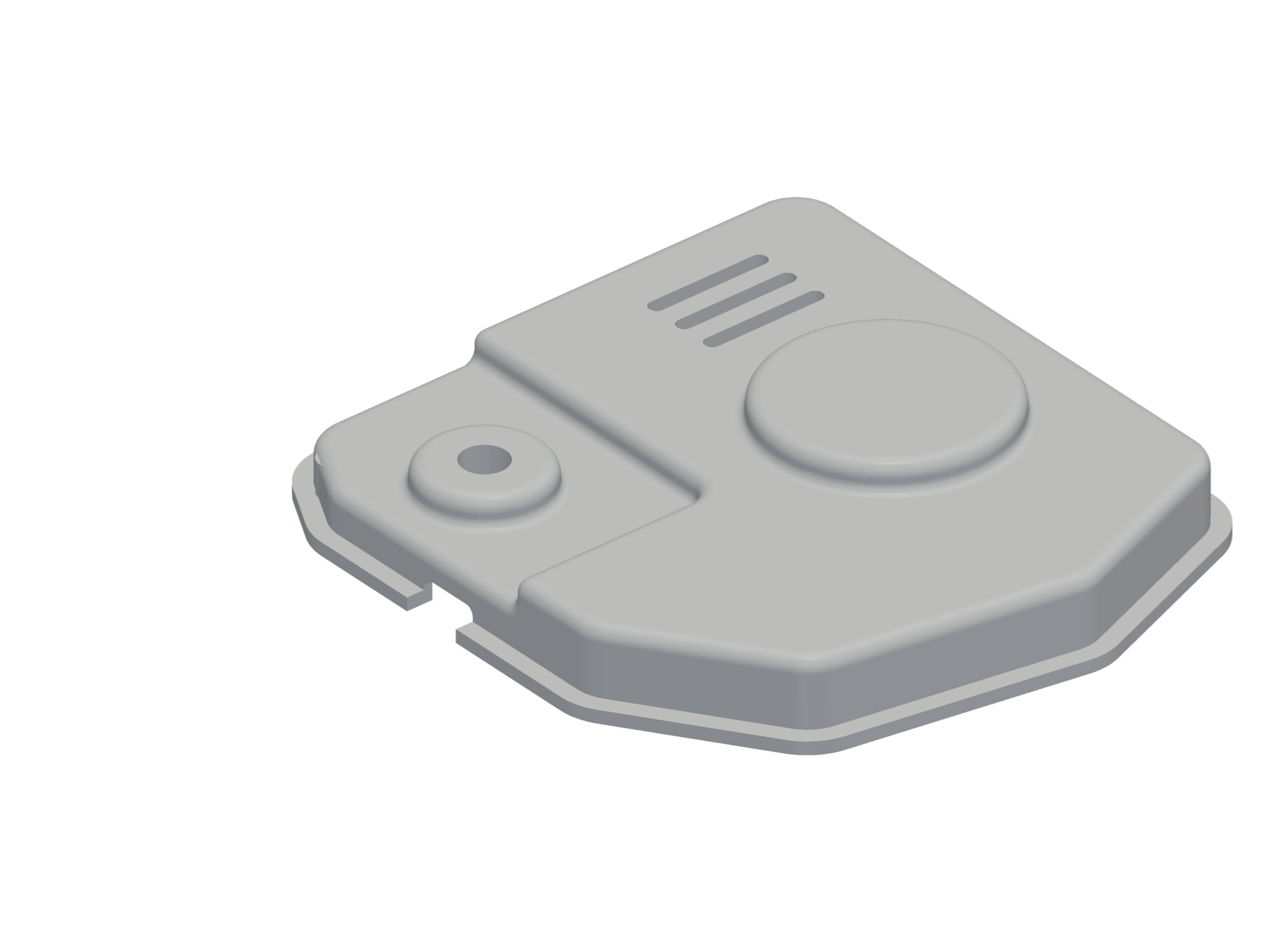
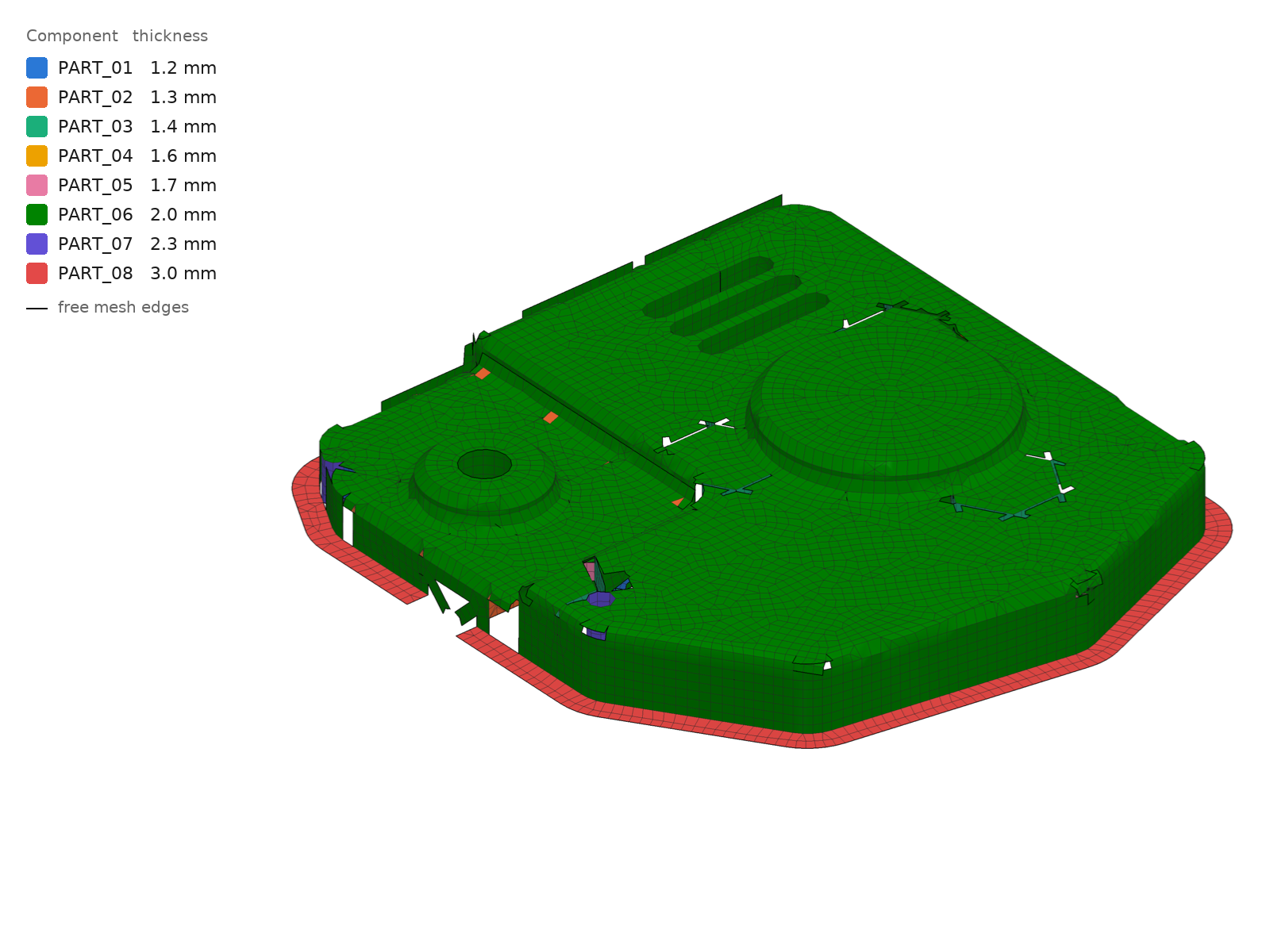
98.06 % coverage, 362 of 450 junctions. Left: the short honeycomb ribs next to the wall (several of them under 30 % covered) and two small regions the engine reports as not made (74 mm² of varying thickness, 20 mm² without a steady opposite wall). The many short ribs give the most small elements of the eight parts: 9.65 % fail a check, mostly the short-edge and angle checks.
Part 2 — Carrier tray
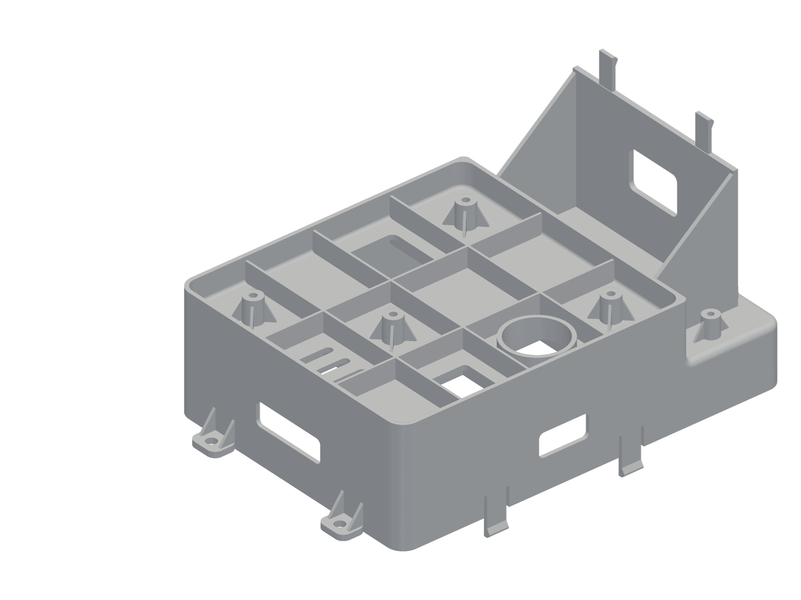
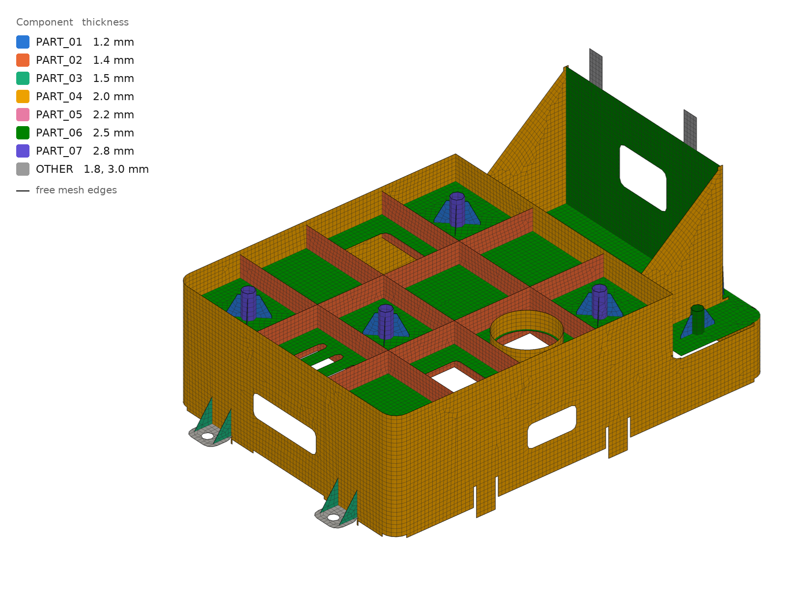
99.25 % coverage, 123 of 129 junctions, every face meshed. Left: the snap hooks (58–62 % covered) and part of the shell blend (86 %).
Part 3 — Gear housing
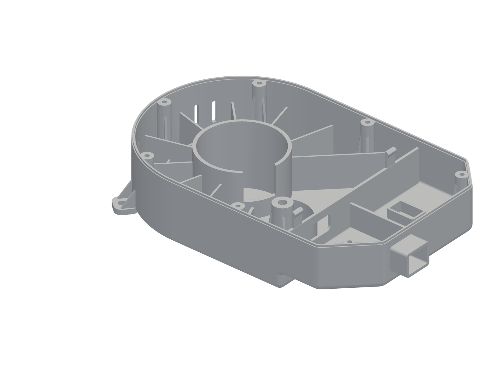
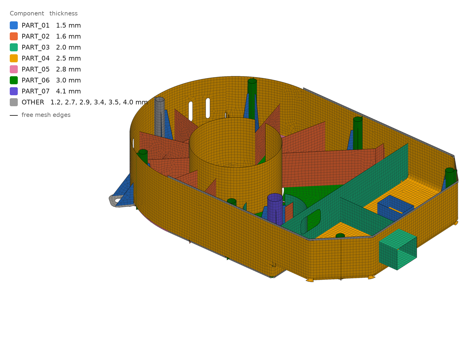
99.63 % coverage, 176 of 184 junctions. Left: the 1.2 mm rim tongue (76 %) and some gusset ends. 9 small faces are not meshed and 68 elements have a corner under 5°; after the STEP round trip the scorer finds 3 faces that fail its validity check.
Part 3B — Gear housing, free-form
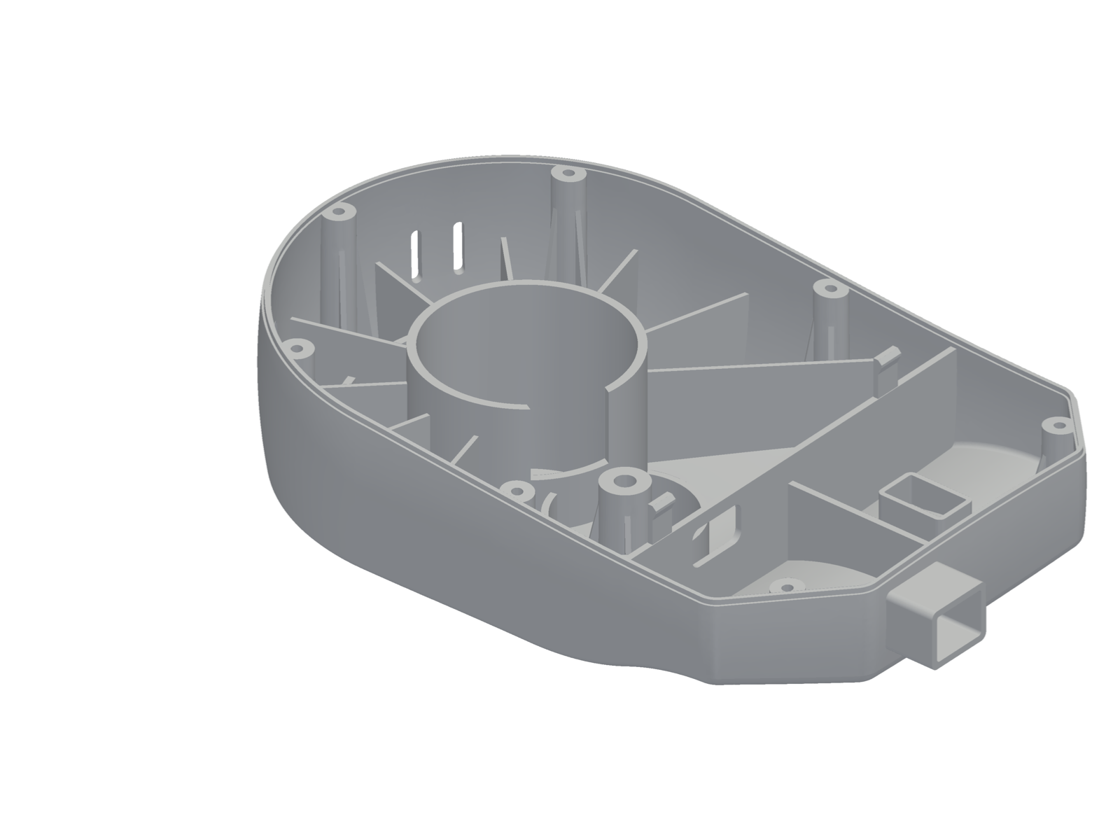
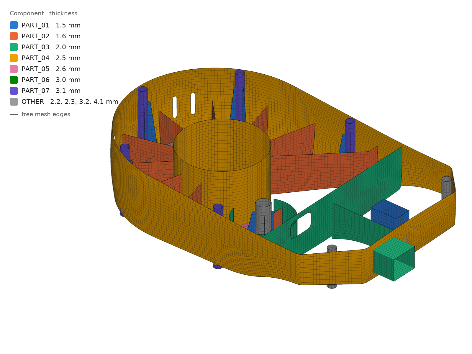
73.67 % coverage, 46 of 128 junctions. The free-form floor (2.57–3.0 mm thick, 15 % spread) and most gussets are left out and reported: 19 regions, 18 of them "varying thickness". The walls that are made are accurate (mean thickness error 0.048 mm) and mesh well (1.05 % failing).
Part 3C — Gear housing, free-form with root fillets
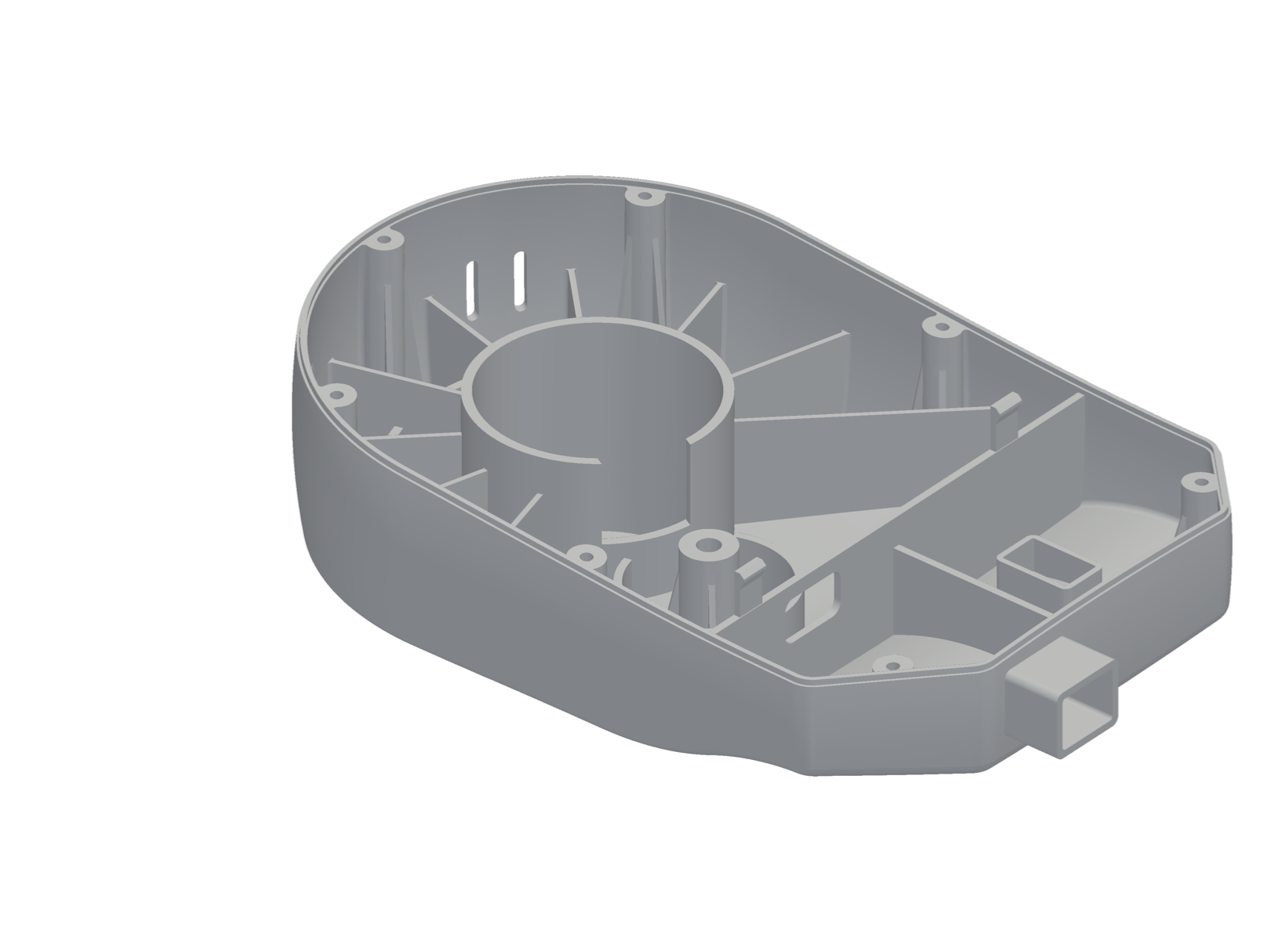
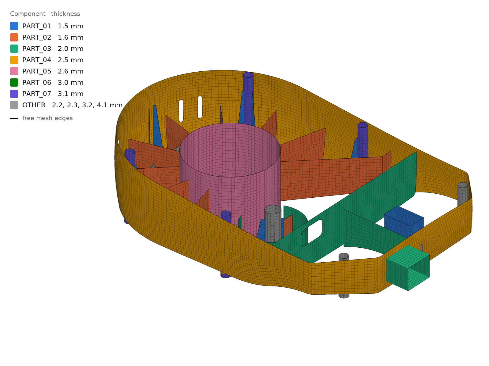
72.32 % coverage, 40 of 128 junctions: as 3B, plus the R1 root fillets, which cost six more junctions. 15 regions reported not made.
Part 4 — Blower scroll
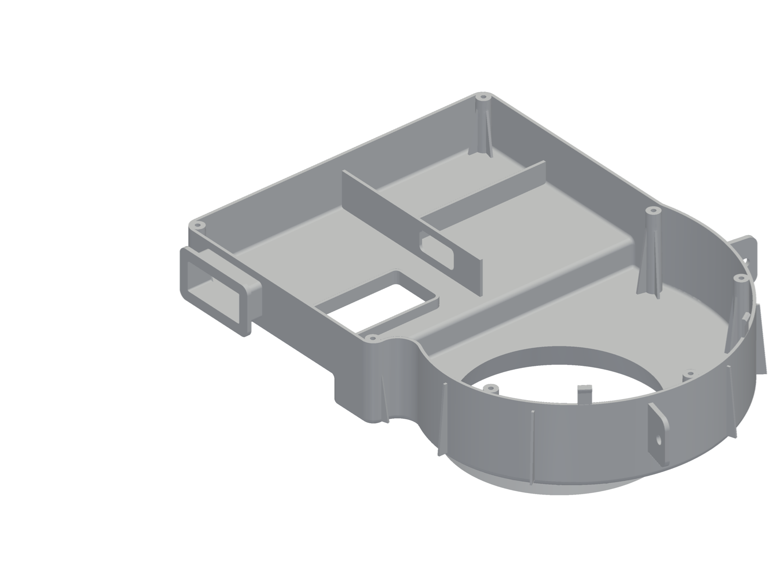
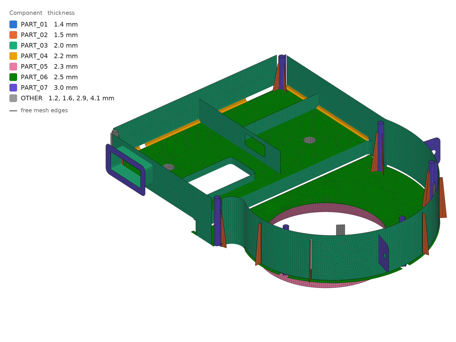
97.30 % coverage, 107 of 140 junctions, every face meshed, 0.86 % of elements failing. Left: the shell blend between walls of different thickness (70 %) and the short strips joining three bosses to the scroll wall (66–71 %).
Part 5 — Pedal bracket
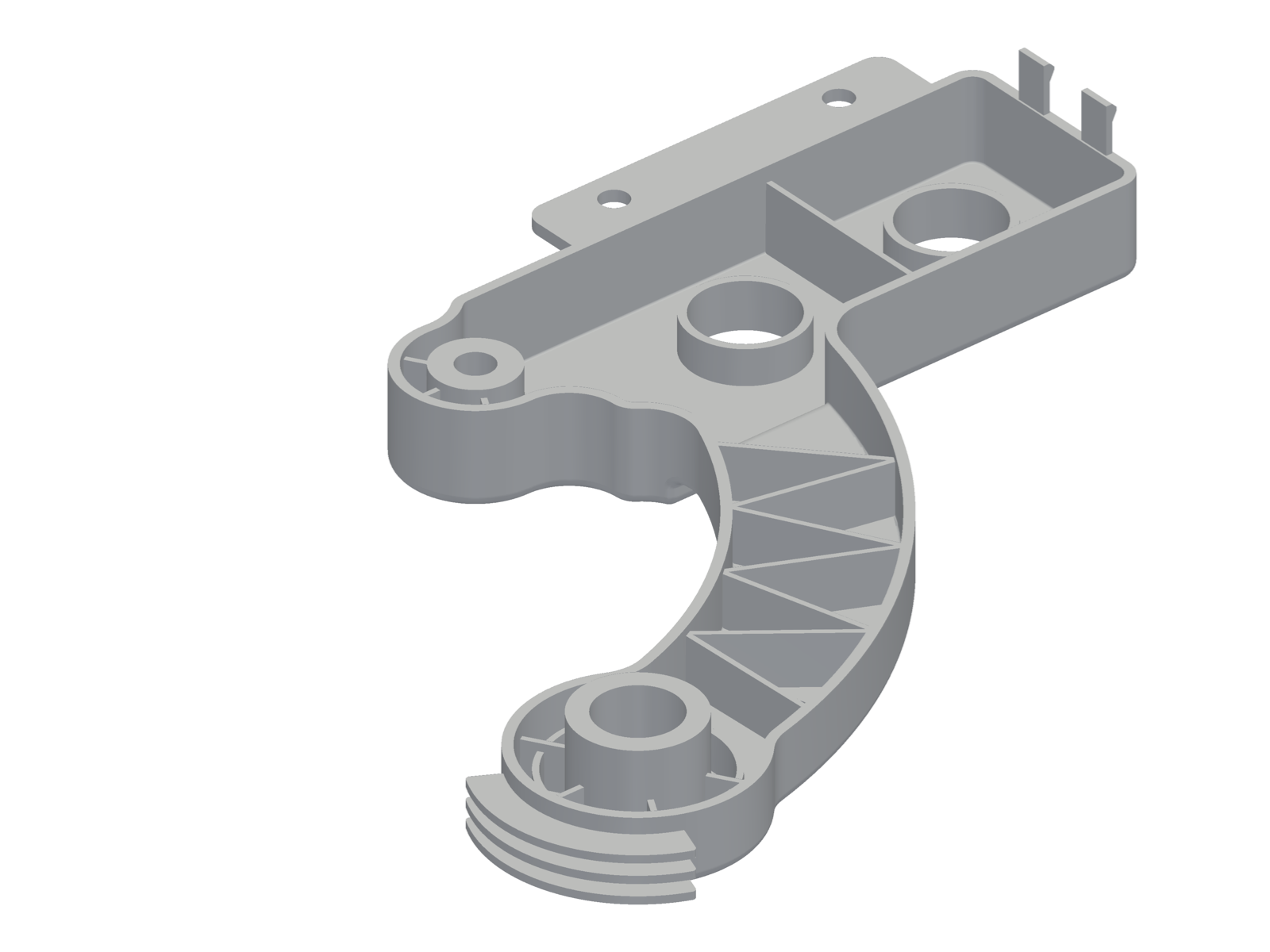
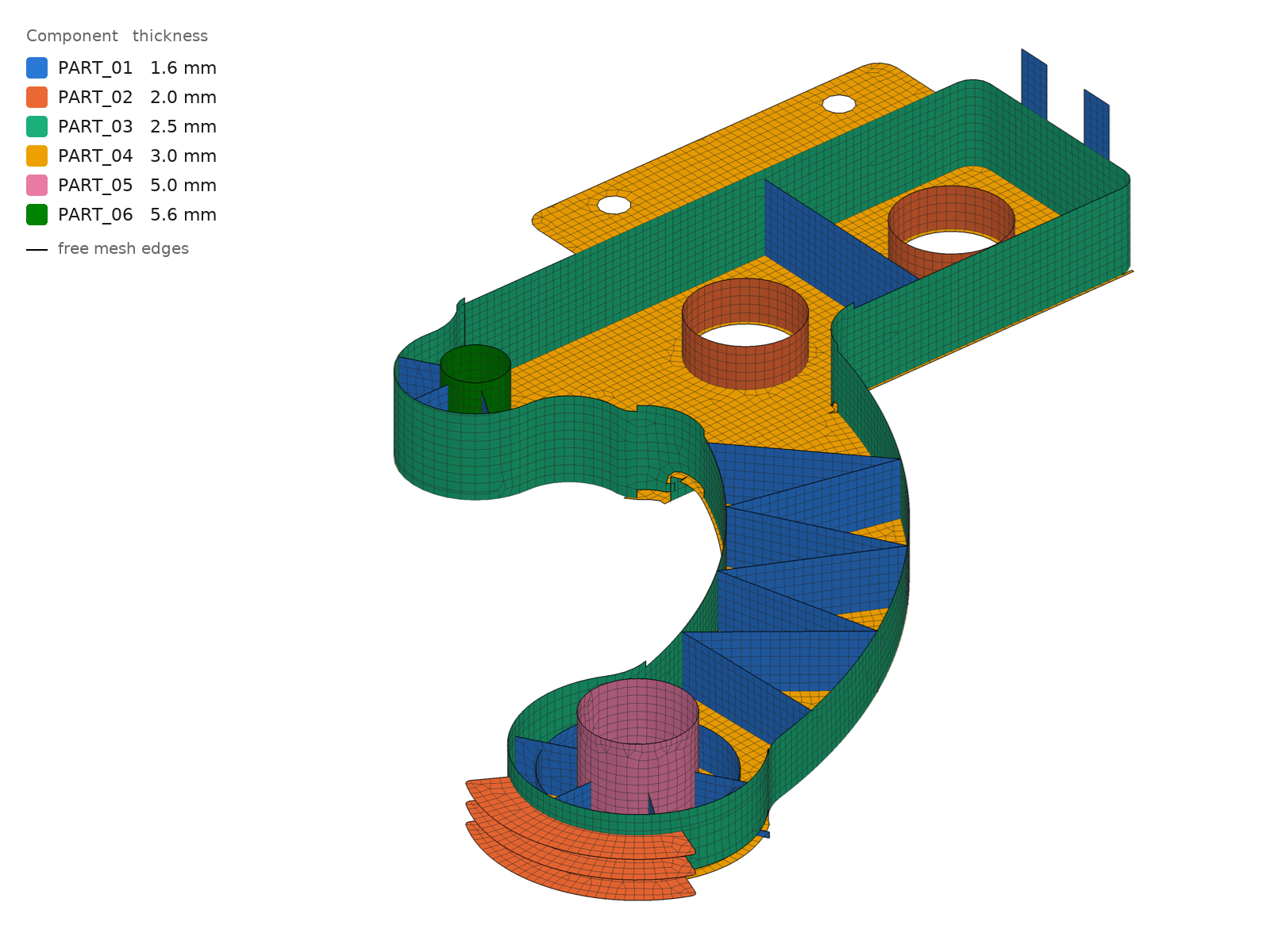
98.87 % coverage, 85 of 86 junctions, every face meshed. Left: part of the outer wall and its blend (97 and 98 %). The largest thickness reading (3.9 mm off, on one rib) is local: the part's mean error is 0.023 mm.
Part 6 — Hinge bracket
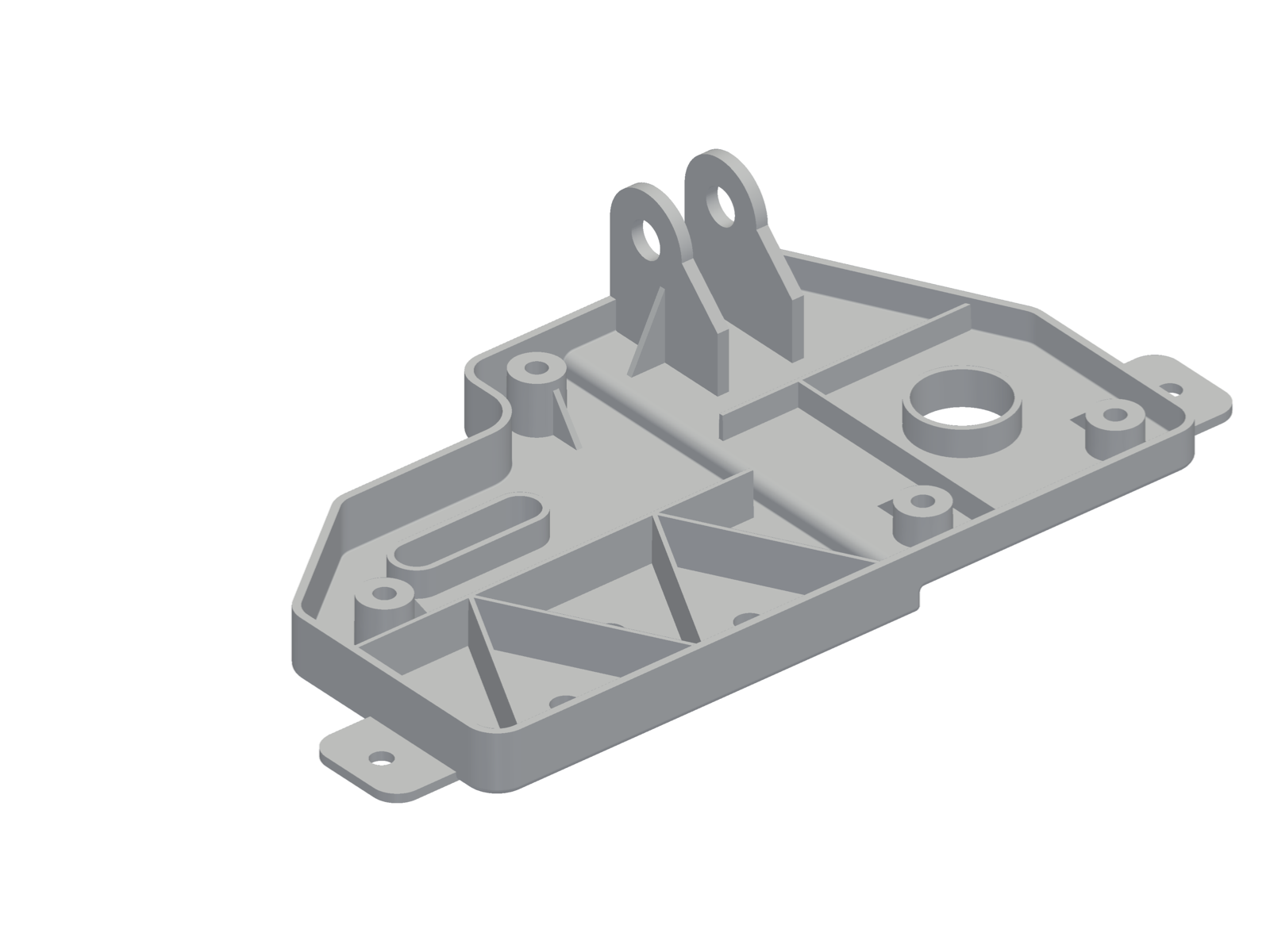
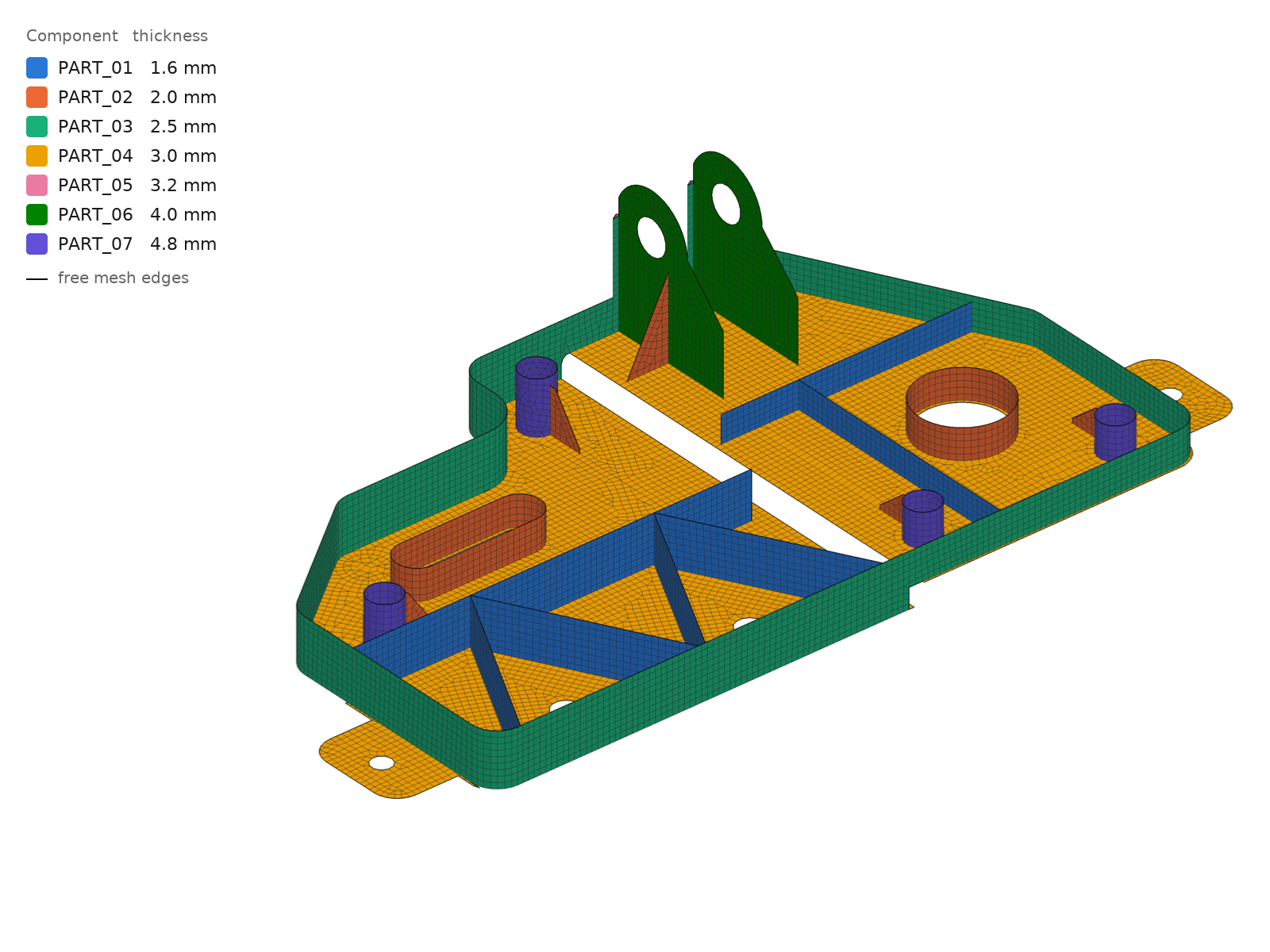
98.20 % coverage, 52 of 53 junctions. Left: the shell blend along the joggle (the white strip in the picture, 396 mm², reported as not made: its thickness varies by 9.9 %). Two faces are not meshed.
Where it's weak and why
- Curved walls of changing thickness are left out, not guessed. This is the whole difference between Part 3 (99.6 %) and Parts 3B/3C (72–74 %): the free-form floor varies from 2.57 to 3.0 mm, and the engine only builds a curved wall when its thickness is steady. The same rule leaves out the blends in Parts 4 and 6. I have a version that offsets such walls by their median thickness (3B: 73.7 % → about 97.7 %), but it makes the run about four times slower and leaves invalid faces on 3B, so it is not in this engine.
- What is left out is reported. BeidPrep shows each such region as "not made", with its area and position, instead of silently returning a midsurface with holes.
- Many short ribs make small elements. Part 1's honeycomb ribs next to the wall are short and close together; their midsurface is only partly made and the mesh there has the highest share of failing elements (9.65 %).
- Junctions next to blends and fillets (3C root fillets, Part 4 boss strips) are the most common missing junctions after the left-out regions.
- The largest single thickness readings (1.2–3.9 mm off, on one rib, gusset or boss per part) are local: the area-weighted mean error stays at 0.015–0.048 mm on every part.
Limits
- These are eight parts I designed. They cover common moulded-part features (ribs, bosses, gussets, drafts, free-form shells, a truss, flanges, a joggle), but they are not a sample of production parts.
- The ground truth is the designed mid-surface. Where two reasonable midsurfaces exist (a boss merged into a wall beside it, a blend between walls of different thickness), the score follows the design choice.
- Coverage counts surface within a tolerance (0.5 mm or t/4); smoothness is judged by the mesh checks.
- The gap count compares open edges with the design's own open edges within 1.5 mm; an open edge that sits a little further from its designed position (at a free edge of a thick wall) can be counted as a gap.
- The mesh checks use one mesher (BeidPrep's beta mesher) at one element size (2 mm); other sizes give other shares.
- Run times come from one cloud machine (7–25 s per part for the engine) and only show the order of size.